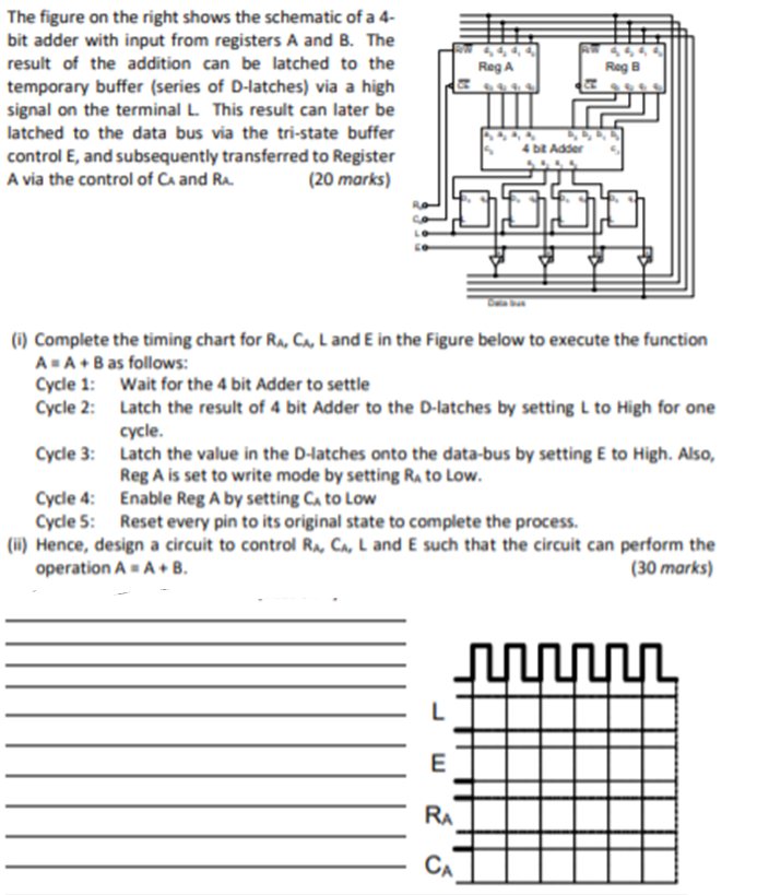
The figure on the right shows the schematic of a 4- bit adder with input from registers A and B. The result of the addition can be latched to the temporary buffer (series of D-latches) via a high s signal on the terminal L. This result can later be atched to the data bus via the tri-state buffer control E, and subsequently transferred to Register A via the control of Ca and
OR
PayPal Gateway not configured
OR
PayPal Gateway not configured